Overview of Voltage Regulator Types (Mosfet vs. Thyristor)
6/1/16
Introduction
The linked material below is a collection of information which provides an overview of both the mosfet and thyristor type voltage regulators. If using a thyristor type voltage regulator and it fails, upgrading to a mosfet based voltage regulator will offer longer lifespan and better charging system performance. Heat buildup in the voltage regulator kills the SCRs, whereas mosfets are more efficient and reliable. In general the mosfet design is better suited for the voltage regulator application demands.
Summary
Mosfet based voltage regulators are the preferred design solution for powersports vehicles. Heat buildup is a major cause of voltage regulator failures. The ideal voltage regulator mounting location would provide cool air flow and are away from exhaust system or engine heat.
When starting a vehicle with a low battery, it will cause the voltage regulator to push high currents for a longer period of time. This duty cycle will cause the voltage regulator to run hotter. Maintaining the Shorai LFX battery above 13.3V will help to reduce stress on the voltage regulator because the charged time to reach 14.4V will be relatively short. If the battery is at 13.1V ~50% SOC or 12.86V~20% SOC this will result in higher voltage regulator temperatures.
For the complete write-up please keep reading.
Voltage Regulators
The Voltage Regulator is an important component of the electrical charging system, and keeps your motorcycle battery from being overcharged and damaged. This section has information on common regulator types and troubleshooting information. There are a few common types of Voltage Regulators used on most motorcycles. The most common is a single or three phase regulator for permanent magnet charging systems. This type is used on the majority of modern street motorcycles. A different style of regulator is used on field coil regulated systems, which are found on many street motorcycles from the 1970's through early 1980's. And finally a very simple regulator is used on alternator type systems. Most Voltage Regulators contain a Rectifier component as well, and they are often referred to as 'Regulator-Rectifiers'. The Rectifier is a separate, but equally important component, which serves to convert ("rectify") the alternating current (AC) produced by the stator & flywheel to direct current (DC) necessary to charge a battery. The different types are explained in more detail below.
Permanent Magnet Flywheel Voltage Regulators
Single Phase Voltage Regulators

Single Phase Voltage Regulators are used with single phase stators in permanent magnet flywheel charging systems. You can see the stators and rotors pages to learn more about these type of systems. The Single Phase Voltage Regulator serves two functions. First, is to act as a Rectifier (why these are often called Regulator-Rectifier’s). The rectifier section is represented by the 4 arrows in the schematic above. The arrows represent the internal Diodes, which are electronic components inside unit which form the Rectifier section. Diodes are a simple electrical component that serve a single function. Diodes can be thought of as one-way streets for electrical current. They only allow current to pass in one direction: positive polarity. The single phase rectifier has each end of the stator coil connected in between a pair of diodes. The diodes filter out the negative portion of the alternating current wave, only allowing the positive polarity current to pass. After the diode bridge, the electrical current from the stator is rectified into direct current, which is used to charge the battery.
The Regulator is separate set of components and function inside the unit. The regulator function is very simple (and reliable) in most motorcycle regulators. A regulator control circuit monitors battery voltage, and compares this measurement to an internal reference voltage (the regulation point). Motorcycle regulators are generally designed to allow a maximum battery voltage of ~14.6VDC at the battery while charging. When this voltage limit is reached, the control circuit triggers semiconductor switches, called 'Silicon Controlled Rectifiers' (SCR's). When the SCR is triggered, it essentially closes a switch, making a connection between the output of the stator, and ground. This act shunts stator output to the ground, which is dissipated as heat throughout the regulators body. This is why the regulator housing design is critical. It not only serves to protect the internal components from the elements & vibration, but needs to efficiently dissipate heat as excess current is bled off. Fins are often used to allow airflow to help cool the housing.
Three Phase Voltage Regulators

Three Phase voltage regulator/rectifiers function the same way as described above in the single phase section. The differences are the rectifier bridge contains another set of diodes to rectify the third phase of output from the stator.
Field Coil Rotor Regulators

These Voltage Regulator units are of the type used on bikes that use a rotor with an internal field coil, instead of a permanent magnet flywheel. This type of system is used on many Japanese motorcycles throughout the 70's and early 80's, like the Honda CB series & Yamaha XS series. These units have an internal rectifier, that functions the same way as the units described above. The difference with this type of system is in the regulation. Regulation in these systems is done by varying the current flow through a field coil inside of the rotor to vary the magnetic field, rather than shunting stator output (see permanent magnet systems above). The regulator senses battery voltage, and regulates current flow to the field coil. When the battery voltage is low, the regulator allows maximum current to flow through the field coil, increasing the magnetic field in the rotor. This, in turn, increases the output from the stator windings. When the measured battery voltage reaches full charge (~14.4V), current flow through the field coil is reduced, or stopped altogether (depending on the particular model), to avoid overcharging the battery. These systems are more efficient than Permanent Magnet charging systems, as there is not as much wasted current being generated that has to be dissipated as heat. However there are more parts to wear out in these systems, such as the slip rings on the rotor, or the brushes providing current to the field coil.
Alternator Regulation
Some motorcycles, particularly street models in the 80's, used an automotive-type alternator system. In these units an alternator is usually gear driven from the crankshaft. The alternator has an internal diode bridge to perform AC->DC rectification (see description above). The alternator has an internal field coil, which is controlled by a separate regulator unit (also internal to the alternator). The regulators can fail on these units, and are easy to replace.
General Voltage Regulator (Regulator/Rectifier) Troubleshooting Steps
Voltage Regulator units generally fail from heat. Most regulators work to protect the battery by dissipating unnecessary charging current as heat. The heat is sunk by the metal body of the regulator. On most bikes, the regulator body is finned for air-cooling, and is mounted in some location with decent airflow. If a regulator fails often on a particular model, and the regulator is mounted in a location with poor airflow (underneath the seat, under a fairing, near exhaust, etc.) it can help to move and re-mount the regulator housing somewhere on the bike with very good airflow.
Regulation Failures
The regulation functions of a Voltage Regulator unit cannot be easily tested. (We offer testing services on our test bench, where we can accurately diagnose a regulator failure. Please contact us to arrange testing services.) Regulation failures will generally present themselves by over-charging the battery. This may be noticeable by blowing up headlight or taillight bulbs from high voltage, or the battery getting extremely hot, and boiling the acid inside. This can be easily diagnosed with a Digital Multi Meter (DMM).
1: Connect your DMM to the battery terminals, Red DMM lead to the Positive (+) terminal, Black DMM lead to the Negative (-) terminal.
2: Set the DMM to DC Voltage mode, 20V range.
3: Start the engine.
4: Note battery voltage at idle. It should be in the range of 12V - 13VDC at idle. (see comment below)
5: Rev the engine to 4000-5000RPM, and check the DMM reading.
6: The regulator should reach ~14.4 - 14.6VDC.
If the voltage continues increasing with RPM over 15VDC, the regulation function is not operating correctly. The regulation function is not serviceable at all, the Voltage Regulator must be replaced. Regulation functions can be intermittent, and get progressively worse. It can be hard to test and be positive of regulator failure, but this is the easiest and most common way to diagnose this failure.
Source - http://racetechelectric.com/ft-751-voltage-regulators.html
In reference to desired voltage at idle – less than 13.2V will discharge LFX batteries, 13.6-14.4V is desired for all RPM ranges. LFX can tolerate up to 15.2V.
The MOSFET
The MOSFET – Metal Oxide FET
As well as the Junction Field Effect Transistor (JFET), there is another type of Field Effect Transistor available whose Gate input is electrically insulated from the main current carrying channel and is therefore called an Insulated Gate Field Effect Transistor or IGFET. The most common type of insulated gate FET which is used in many different types of electronic circuits is called the Metal Oxide Semiconductor Field Effect Transistor or MOSFET for short.

Source - http://www.electronics-tutorials.ws/transistor/tran_6.html
SCR (Thyristor)

An SCR, or Silicon Controlled Rectifier, is a semiconductor, or integrated circuit (IC), that allows the control of current using a small current. Basically, it is a simple direct current (DC) light switch.
Simple Thyristor Circuits Explained
written by: Swagatam • edited by: Lamar Stonecypher • updated: 11/14/2011
The article relates the technical specifications of SCRs and their working principles through an easy to understand, step-wise explanation. The article also offers a few interesting SCR projects that can be easily built and used for the relevant purposes.
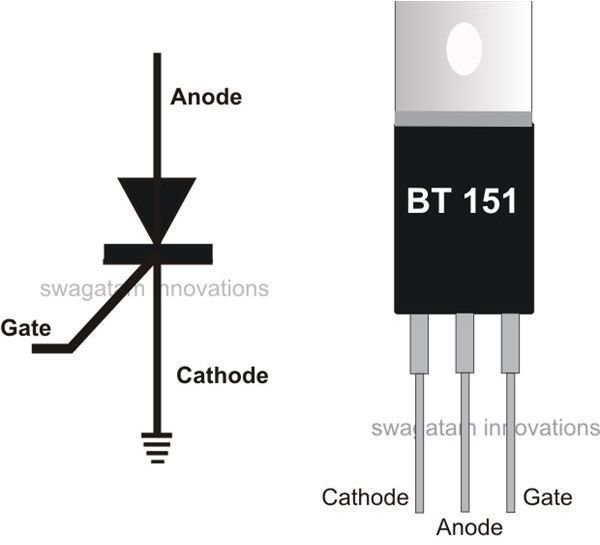
SCRs or Silicon Controlled Rectifiers are members of the electronic active component family. They are also called Thyristors. The figure on the left shows the standard electronic symbol of an SCR. It shows the three lead pin outs of the part, the upper one being the anode, the lower one the cathode, and the central extension the gate. The symbol quite resembles an ordinary rectifier diode symbol having an extra lead from the cathode side. Though SCRs are much different from diodes, they too rectify AC in response to DC electrical triggers on their gate inputs.
As you can see in the actual picture of an SCR on the right, it looks like a transistor. Externally they may look exactly like transistors, but are entirely different as far as technical specifications are concerned.
Both act as switching devices, although SCRs comfortably handle high voltage AC, whereas transistors normally are dedicated for low voltage DC applications. The lead orientation specifies the first lead from the right to be the gate, the extreme left is the cathode, and the center pin is the anode. The gate and the anode leads always work with respect to the ground; the cathode lead is specified to be connected with the ground and serves as the common release terminal for the gate as well as the anode. The load that needs to be operated is connected across the AC input and the anode of the SCR.
How SCRs Function
Unlike transistors, which may show an exponentially varying output current pattern, equivalent to the applied input switching current, SCRs have specific triggering levels below which they may not conduct properly. However, once the trigger level crosses the optimal value, an SCR may swing into full conduction.
Another typical property associated with SCRs is their “latching" behavior with DC operated loads, where the anode to cathode conduction through the load latches or “holds-on" even after the gate trigger is inhibited. However, with AC operated loads the above drawback, or rather benefit, is not available and the load is switched ON or OFF exactly in response to the switching of the SCR’s gate triggers.
Summary
Mosfet based voltage regulators are the preferred design solution for powersports vehicles. Heat buildup is a major cause of voltage regulator failures. The ideal voltage regulator mounting location would provide cool air flow and are away from exhaust system or engine heat.
When starting a vehicle with a low battery, it will cause the voltage regulator to push high currents for a longer period of time. This duty cycle will cause the voltage regulator to run hotter. Maintaining the Shorai LFX battery above 13.3V will help to reduce stress on the voltage regulator because the charged time to reach 14.4V will be relatively short. If the battery is at 13.1V ~50% SOC or 12.86V~20% SOC this will result in higher voltage regulator temperatures.